
At Tube Aligen Pro we provide all technical data about the piping industry. Piping systems are the veins and arteries of industrial infrastructure, transporting liquids, gases, and steam across vast distances. Pipe fittings need most of the attention; the unsung heroes holding these systems together are flanges. A flange is a method of connecting pipes with each other, valves, pumps, and other equipment to form a piping system. It also gives easy access for cleaning, inspection, or modification.
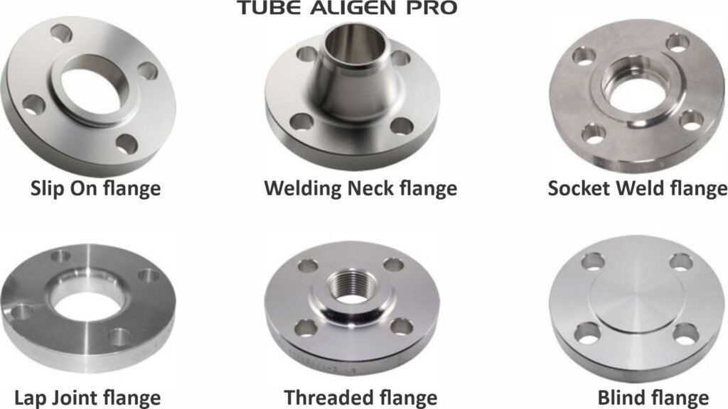
Knowing the different flange types is difficult for engineers, pipefitters, and procurement specialists. The right choice ensures the integrity of the system, preventing leaks and handling specific pressures and temperatures. The most used flange types, particularly under the ASME B16.5 standard, include Welding Neck, Slip On, Socket Weld, Lap Joint, Threaded, and Blind flanges.
1. Welding Neck Flange
The Welding Neck flange, often referred to as a high hub flange, is designed to transfer stress to the pipe, thereby reducing high stress concentrations at the base of the flange.
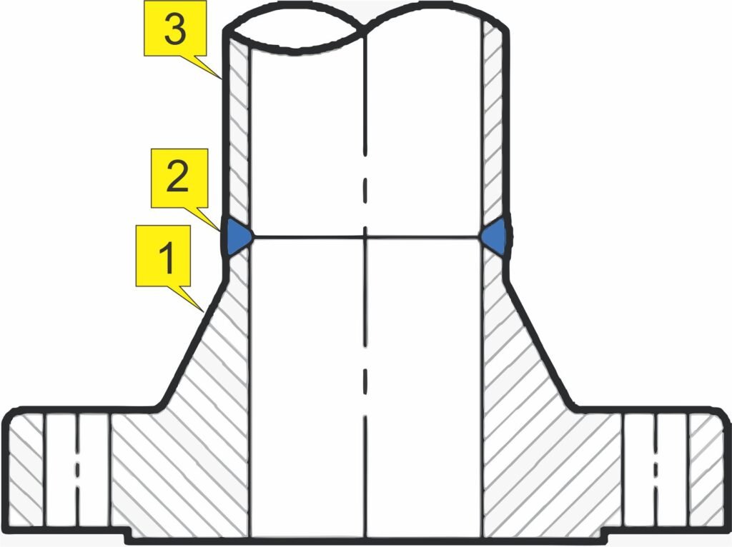
1.Weld Neck flange 2.Butt Weld 3.Pipe or Fitting
Design and Application
This flange is distinguished by its long tapered hub, which goes gradually over to the wall thickness from a pipe or fitting. This design reinforces the flange itself and provides a smooth transition of stress from the flange thickness to the pipe wall. They are ideal for severe service conditions, such as high pressure, sub-zero or elevated temperatures, and fluids that are hazardous or volatile.
Because the inside diameter of the flange matches the inside diameter of the pipe, there is no restriction of flow. This prevents turbulence at the joint and reduces erosion. They are connected to the pipe by a single V-shaped butt weld.
Key Considerations
When specifying these, you might encounter terms like EN1092 1 type 11, which is the European standard equivalent for a weld neck flange. Whether you need a standard ASME B16.5 flange or a 6BX flange for high-pressure API applications, the welding neck offers superior structural integrity.
2. Slip On Flange
A bi slip on flange (or simply “slip on”) is popular because of its low material cost and ease of alignment.
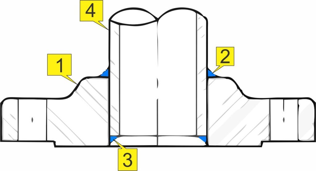
1.Slip On flange 2.Filled weld outside 3.Filled weld inside 4.Pipe
Design and Application
The Slip On flange has a low hub and slips directly onto the pipe prior to welding. It is welded both on the inside and the outside to provide sufficient strength and prevent leakage. These flanges are typically used in low-pressure applications and are not recommended for high stress or severe fatigue conditions.
For example, a 2 slip on flange is a common component in general utility lines like cooling water or low-pressure compressed air. They are easier to align than weld neck flanges because the pipe slips into the flange before welding.
Pros and Cons
While economical, their strength is approximately two-thirds that of a welding neck flange, and their fatigue life is about one-third. However, in non-critical systems, the cost savings and ease of installation make them a staple.
3. Socket Weld Flange
Socket Weld flanges were initially developed for use on small-size high-pressure piping.
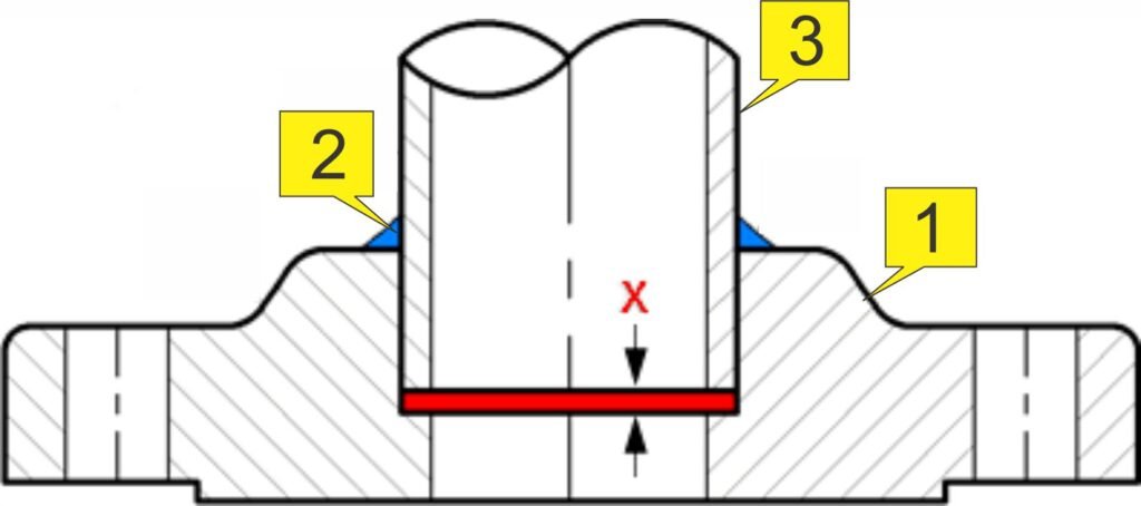
1.Socket Weld flange 2.Filled weld 3.Pipe X = Expansion gap
Design and Application
These flanges have a recessed area (the socket) into which the pipe is inserted. They are attached using a single fillet weld on the exterior. This design eliminates internal pockets where fluid could stagnate, making them suitable for some food and beverage or chemical applications, though they are primarily used for small-bore piping.
One major benefit is that they do not require the beveling of the pipe preparation, which simplifies installation compared to butt-weld flanges.
4. Lap Joint Flange
The Lap Joint flange is unique because it consists of two parts: the stub end and the loose backing flange.
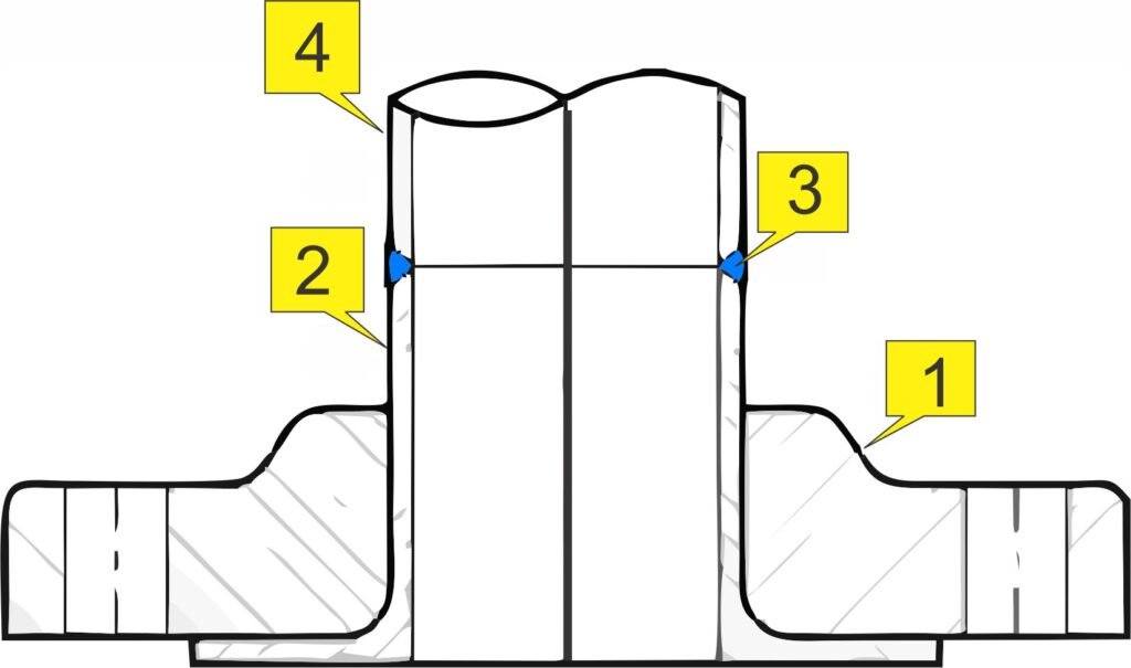
1.Lap Joint flange 2.Stub End 3.Butt weld 4.Pipe or Fitting
Design and Application
A backing flange and stub end assembly allows the flange to rotate freely around the stub end, which makes aligning bolt holes much easier—a significant advantage in complex piping systems where alignment is difficult.
The stub end is welded to the pipe, while the backing flange remains loose. This is particularly useful in systems requiring frequent dismantling for inspection or cleaning. For instance, a 1 2 lap joint setup might be used in a section of pipe that needs regular maintenance.
Cost Efficiency
Because the backing flange does not come in contact with the process fluid, it can be made of a less expensive material (like carbon steel) while the stub end matches the corrosion-resistant material of the piping system (like stainless steel). This makes the Lap Joint flange an economical choice for expensive alloy systems.
5. Threaded Flange
Threaded flanges look similar to Slip On flanges but are threaded inside the bore.
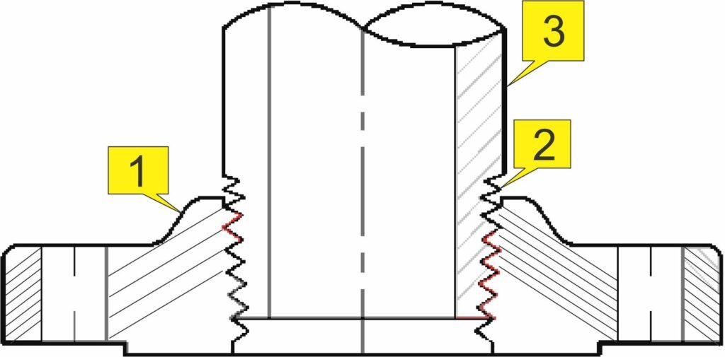
1.Threaded flange 2.Thread 3.Pipe or Fitting
Design and Application
The main advantage of a threaded flange is that it can be assembled without welding. This makes them essential in explosive areas where welding is hazardous (like refineries or grain elevators) or in remote locations where welding equipment is not available.
They are typically used on smaller pipe sizes and low-pressure ratings. However, specialized versions exist for specific needs, such as a blind flange with NPT thread or blind flange with 1 2 NPT for instrument connections.
6. Blind Flange
Unlike the other types, a blind flange has no bore. It is used to blank off the ends of piping, valves, and pressure vessel openings.
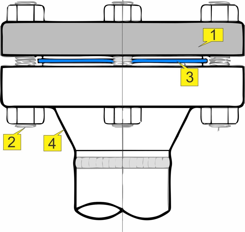
1.Blind flange 2.Stud Bolt 3.Gasket 4.Other flange
Design and Application
From a standpoint of internal pressure and bolt loading, blind flanges, particularly in larger sizes, are the most highly stressed flange types. However, most of these stresses are bending types near the center, and since there is no standard inside diameter, these flanges are suitable for higher pressure temperature applications.
A blind flange connection allows for easy access to the interior of a line or vessel once it has been unbolted. You might see a 150 blind flange (referring to Class 150 pressure rating) capping the end of a water line, or a massive high hub blind flange used in high-pressure petrochemical reactors. Other variations include the bossed blind flange, which provides a connection point for drains or instruments.
Types of Blind Flanges
- Ring Joint Blind Flanges
- Raised Face Blind Flanges
- Flat Face Blind Flanges
- Close Nipple Blind Flanges
- Weld Neck Blind Flanges
Valve Connections and Flange Compatibility
Flanges are not just for connecting pipe to pipe; they are the standard interface for connecting valves. Understanding how different valves interface with flanges is crucial.
Gate and Globe Valves
In isolation applications, you will often find a 2 flanged gate valve or a gate valve 3 inch flange type. These valves have flanged ends drilled to match the mating pipe flanges. Similarly, a cast iron globe valve flanged type or a bronze flanged gate valve provides reliable flow throttling and isolation.
For larger municipal water systems, double flanged gate valve designs are common. The “double flanged” designation simply means the valve has a flange on both the inlet and outlet, allowing it to be bolted directly into the pipeline.
Butterfly and Check Valves
Butterfly valves are often sandwiched between flanges. A double flange type butterfly valve or butterfly valve double flange type has a complete flange body that is bolted to the pipe flange on both sides. This is distinct from wafer-style valves that are held in place by long bolts compressing them between two pipe flanges.
Check valves, which prevent backflow, also rely on flanged connections. A double flange check valve or dual plate check valve flange type ensures that flow only moves in one direction while providing a robust, leak-free seal. In some setups, a CI foot valve flange type (Cast Iron) is installed at the intake of a pump suction line to maintain prime.
Standards and Pressure Ratings
When specifying flanges, you must adhere to international standards to ensure compatibility.
ASME and API Standards
In the United States, ASME B16.5 is the gold standard for pipe flanges. However, the oil and gas industry often relies on API standards. For example, API 6A Type 6B and API 6A Type 6BX flanges are designed for extremely high pressures found in wellhead and Christmas tree equipment. The 6BX flange usually has a raised face and is designed for ring joint gaskets to handle pressures up to 20,000 PSI.
European Standards (DIN/EN)
In Europe and many other parts of the world, the EN 1092-1 standard prevails. You will frequently see designations like EN1092 1 PN16 flange or EN1092 PN10. The “PN” stands for “Pressure Nominal.”
- DN65 PN16 flange: This refers to a flange with a nominal diameter (DN) of 65mm and a pressure rating of 16 bar.
- DN150 PN16 flange: A larger 150mm flange with the same pressure rating.
- DIN 2501 PN10: An older German standard still commonly referenced for 10-bar flanges.
Understanding the cross-compatibility (or lack thereof) between a Class D flange (an older British standard) and an EN1092 1 PN10 flange is vital for retrofitting older plants.
Specialized Components and Materials
Beyond the basic types, specific components solve unique piping challenges.
Material Choices
While carbon steel is standard, specific environments require different materials. A double flanged DI pipe (Ductile Iron) is standard in water, sewer, and irrigation systems due to its durability and corrosion resistance. In plumbing systems, you might encounter a 4 propress flange, which uses a press-to-connect copper fitting adapted to a flange, speeding up installation significantly.
Reducing and Blanking
Sometimes you need to change line sizes at a flanged connection. A double flange reducer allows you to bolt a larger flange to a smaller one, safely reducing the pipe diameter.
If you need to permanently or temporarily close a line, a 16 blind flange (16-inch) or an ASME blind flange offers a secure seal. For testing purposes, a blind flange PN16 might be installed to pressure test a specific section of a pipeline.
High-Tech Seals
For critical sealing, the gasket surface matters. While standard flanges usually have a raised face, high-pressure API 6A Type 6BX flanges utilize ring joint gaskets (RTJ). These metal gaskets deform under bolt load to create a metal-to-metal seal that can withstand immense pressure.
Tips for Flange Selection
Selecting the right flange involves more than just picking a type. You must consider the pressure-temperature rating, material compatibility, and the fluid being transported.
- Identify the Standard: Are you working with ASME, API, or EN standards? An EN1092 1 PN16 flange will not bolt up to an ASME Class 150 flange because the bolt hole patterns and diameters are different.
- Check the Pressure: Ensure the flange rating exceeds the maximum system pressure. A blind flange valve setup used for isolation must handle the full upstream pressure.
- Material Matters: Match the flange material to the pipe. Using a carbon steel double flange valve on a stainless steel line can lead to galvanic corrosion.
- Gasket Selection: The flange face determines the gasket. A flat-faced 1092 1 flange requires a full-face gasket, while a raised face flange uses a ring gasket.
FAQ
Conclusion
From the robust Welding Neck to the versatile double flange type butterfly valve, flanges are integral to industrial safety and efficiency. Whether you are designing a new chemical plant using EN1092 PN16 components or replacing a gate valve 3 inch flange type in an HVAC system, knowing your options ensures you make the right call.
The vast array of terminology—from bossed blind flange to butterfly valve flange connection—can be daunting. However, by focusing on the application’s pressure, temperature, and fluid requirements, you can navigate these choices with confidence. Always consult the relevant ASME B16.5 or EN 1092-1 charts to verify dimensions and ratings before ordering materials.